使用惠斯通电桥Wheatstone bridge 搭建柔性电子器件测量平台
使用惠斯通电桥Wheatstone bridge 搭建柔性电子器件测量平台
Bin Lian安装依赖
1 | pip install pyvisa |
查看电脑上可使用的端口
1 | import pyvisa |
示例输出:
1 | ('ASRL/dev/cu.debug-console::INSTR', 'ASRL/dev/cu.MilkyWays::INSTR', 'ASRL/dev/cu.Bluetooth-Incoming-Port::INSTR', 'USB0::1689::874::C101038::0::INSTR') |
控制gui编写,使用Trae,只用了一天完成所有code编写
在这里很多非常精华的点可以记录,找时间整理,收获颇丰
oscilloscope 遇到的问题
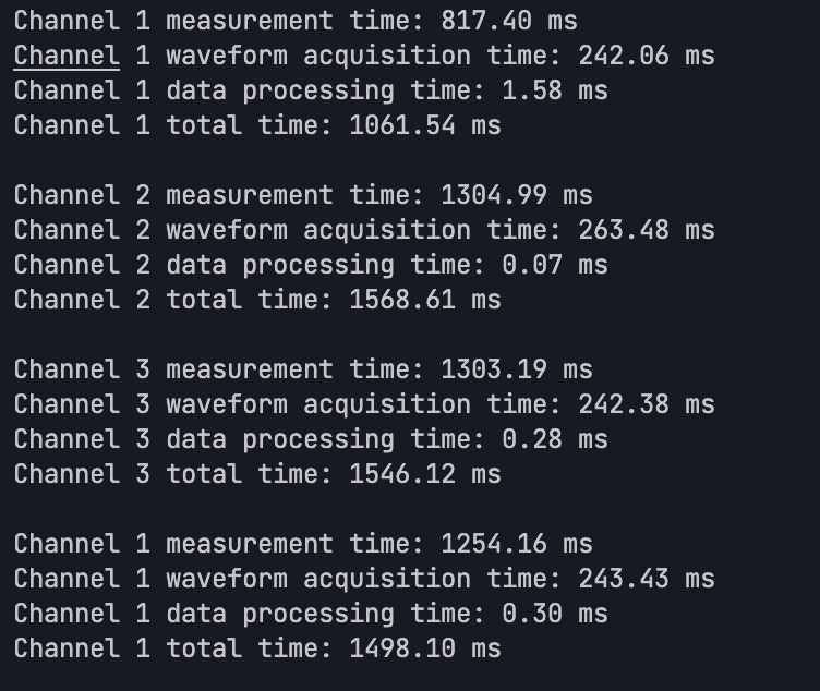
– 写入速度很慢,无法及时写入信号,可能直接传入wavform有关系
处理速度优化
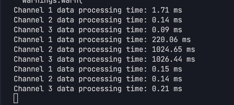
示波器传输速率似乎太慢无法满足要求,改用arduino
让我解释一下 Arduino 的参考电压选项:
使用 arduino 作为oscilloscope
(需要添加示意图)
-
默认情况(不设置 analogReference):
- 使用 5V 作为参考电压
- ADC 范围:0-1023 对应 0-5V
-
使用 EXTERNAL:
- 需要在 AREF 引脚上提供外部参考电压
- 如果没有连接,读数会不稳定或保持在最大值
建议修改代码如下:
1 | const int CHANNELS[] = {A0, A1, A2}; // 模拟输入引脚 |
主要修改:
-
移除了 analogReference(EXTERNAL)
-
添加了电压转换计算
-
输出实际电压值而不是原始 ADC 值
如果您之后需要使用外部参考电压,请确保: -
正确连接 AREF 引脚到稳定的参考电压源
-
参考电压值不超过 5V
-
添加去耦电容到 AREF 引脚
问题总结:
使用低通滤波 (rc low pass) 做信号过滤,选用 4.7kohm R 0.15uF C 来进行设计,截止频率225.75 Hz左右,达到设计要求
四通道中有一个通道响应明显滞后
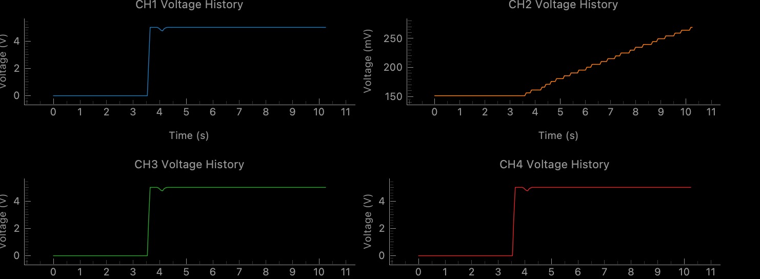
通道2在接通开路电压后,应该如其他通道一般迅速到达哦5v而现在是缓慢增长,电容充电过慢的嫌疑
原因:电桥的探测信号线接触异常,松动,压紧解决
导出干净的requirement 文件
1 | pip freeze | grep -v "@" | grep -v ".whl" > requirements.txt |
实现了线性纳米线控制(使用电压阈值
Reference
DIY Arduino Oscilloscope | Arduino Project Hub
知识点记录:
Understanding Key Components for Arduino Oscilloscope Project
Analog-to-Digital Converters (ADCs)
An ADC converts continuous analog signals (like voltage) into discrete digital values that your microcontroller can process. Think of it as a translator between the analog world (your input signals) and the digital world (Arduino).
Key ADC Specifications to Consider:
-
Resolution: Measured in bits (8-bit, 10-bit, 12-bit, etc.)
- Arduino Uno/Nano: 10-bit (1024 values from 0-1023)
- Arduino Due: 12-bit (4096 values from 0-4095)
- External ADCs like ADS1115: Up to 16-bit
-
Sampling Rate: How many conversions per second
- Arduino Uno/Nano: ~10,000 samples/second maximum
- Arduino Due: ~1,000,000 samples/second maximum
- ESP32: ~2,000,000 samples/second maximum
-
Input Range: The voltage span that can be measured
- Arduino boards typically handle 0-5V or 0-3.3V
- For your oscilloscope, you might need to detect signals outside this range
External ADC Options for Your Project:
- ADS1115: 16-bit precision, but slower (~860 samples/second)
- ADS1015: 12-bit, faster (~3,300 samples/second)
- MCP3208: 12-bit, 8 channels, SPI interface (~100,000 samples/second)
Operational Amplifiers (Op-Amps)
Op-amps are versatile analog components that will help you condition your input signals before they reach the ADC.
Why You Need Op-Amps:
- Signal Conditioning: Adjusting voltage levels to match ADC input range
- Impedance Buffering: Preventing your measurement circuit from affecting the signal
- Filtering: Removing unwanted noise
- Amplification: Boosting weak signals
Recommended Op-Amps for Arduino Projects:
- MCP6004: Quad op-amp (4 channels), rail-to-rail operation, works with 5V supply
- LM324: Affordable quad op-amp, but not rail-to-rail
- TL074: Good for audio frequencies, low noise
- AD8607: Precision, low-noise, but more expensive
Basic Op-Amp Circuit for Your Project:
1 | Input Signal ----[R1]----+----[R2]----+ |
This is a basic non-inverting amplifier where gain = 1 + (R2/R1).
For a 4-channel system, you’ll need one op-amp circuit per channel. The MCP6004 contains four op-amps in one package, making it ideal for your application.
Direct Port Manipulation (DPM) and Finding Addresses
DPM lets you directly access microcontroller registers for faster I/O operations than using standard Arduino functions.
Finding Register Addresses:
-
Consult the microcontroller datasheet:
- For Arduino Uno (ATmega328P): ATmega328P Datasheet
- For Arduino Due (SAM3X8E): SAM3X8E Datasheet
-
For Arduino Due specific to ADC registers:
ADC->ADC_MR: ADC Mode Register (controls ADC behavior)ADC->ADC_CHER: ADC Channel Enable Register (enables specific ADC channels)
-
For Arduino Uno/Mega:
ADMUX: ADC Multiplexer Selection Register (selects input channel)ADCSRA: ADC Control and Status Register A (controls ADC operation)
Example of Finding and Using These Addresses:
For Arduino Due, the registers are already defined in the SAM3X library headers. You can directly use:
1 | ADC->ADC_MR |= 0x80; // Set FREERUN mode |
For Arduino Uno/Mega, you would use:
1 | ADMUX = (ADMUX & 0xF0) | (channel & 0x0F); // Select ADC channel |
Understanding 0xFF and Hexadecimal Notation
0xFF is a hexadecimal (base-16) representation of the decimal number 255 (or binary 11111111).
Hex Notation Explained:
0xprefix indicates a hexadecimal number- Hex uses digits 0-9 and letters A-F (representing values 10-15)
- Each hex digit represents 4 bits
Common Hex Values in Microcontroller Programming:
0xFF= 255 (all 8 bits set to 1)0x00= 0 (all 8 bits set to 0)0x0F= 15 (lower 4 bits set to 1, upper 4 bits set to 0)0xF0= 240 (upper 4 bits set to 1, lower 4 bits set to 0)
How It’s Used in Your Code:
1 | // In binary packet creation: |
Here, & 0xFF is a bitwise AND operation that masks out all but the lowest 8 bits, ensuring you only get one byte of data.
Direct Memory Access (DMA)
DMA is a feature that allows data transfers between memory and peripherals without using the CPU, freeing it for other tasks.
Benefits for Your Oscilloscope Project:
- Higher Throughput: Can continuously stream ADC samples to memory
- Reduced CPU Load: CPU doesn’t need to manually fetch each sample
- More Consistent Timing: Sampling isn’t affected by other code execution
- Background Operation: Your main code can process data while new samples are being collected
Using DMA with Arduino Due:
The Arduino Due (with SAM3X8E) supports DMA through its Peripheral DMA Controller (PDC).
1 | // Basic DMA setup for ADC on Arduino Due |
For ESP32 (Alternative with Better DMA):
The ESP32 has excellent DMA capabilities through its I2S peripheral, which can be repurposed for ADC sampling:
1 |
|
Putting It All Together for Your Oscilloscope
For your 4-channel oscilloscope with 10ms signal detection and sub-1s latency requirements, I recommend:
- Hardware: Arduino Due or ESP32 for their better ADC capabilities and DMA support
- Signal Conditioning: One MCP6004 quad op-amp configured for appropriate scaling
- Sampling Strategy: Use DMA for continuous acquisition
- Data Transfer: Binary packet format for efficient USB communication
The key to meeting your performance requirements will be optimizing both the sampling rate (which needs to be at least 100Hz for 10ms resolution) and the data transfer protocol to maintain latency under 1 second.
Would you like me to elaborate further on any of these aspects or provide a more complete implementation example?
Understanding AREF (Analog Reference) Function in Microcontrollers
AREF, which stands for Analog REFerence, is a critical function in microcontrollers that establishes the voltage reference point for analog-to-digital conversions. This reference voltage directly affects the accuracy and range of your analog sensor readings.
How AREF Works
When a microcontroller like Arduino reads an analog signal, it compares the input voltage to a reference voltage. The analog-to-digital converter (ADC) then maps this voltage to a digital value within its resolution range (typically 0-1023 for 10-bit ADCs).
For example, with a 5V reference:
- 0V input → digital value 0
- 2.5V input → digital value 512 (approximately half)
- 5V input → digital value 1023 (maximum)
However, if you change the reference to 3.3V:
- 0V input → still digital value 0
- 1.65V input → digital value 512
- 3.3V input → digital value 1023
AREF Sources in Arduino
Microcontrollers typically offer several reference voltage options:
- DEFAULT: Usually 5V (or 3.3V on 3.3V boards)
- INTERNAL: An internal reference (often 1.1V on ATmega chips)
- EXTERNAL: Voltage applied to the AREF pin (must be between 0V and VCC)
Why Use Different References?
Changing the reference voltage helps optimize precision for specific measurement ranges:
- For small voltage measurements: Using a lower reference (like 1.1V internal) gives better resolution for small voltages.
- For precise measurements: An external high-quality voltage reference can provide more accurate readings than the sometimes noisy power supply.
- For battery-powered projects: Using internal reference avoids measurement drift as battery voltage decreases.
How to Use AREF in Arduino
1 |
|
When using external reference, you must connect a stable voltage source to the AREF pin. This voltage must not exceed the microcontroller’s operating voltage (VCC).
Practical Implementation Tips
- Never change reference with AREF connected: Always disconnect external references before changing the reference mode to avoid damaging the microcontroller.
- Add capacitor for stability: A small capacitor (0.1μF) between AREF and GND can help stabilize the reference voltage.
- Precision matters: For higher accuracy, use precision voltage references like TL431 or dedicated reference ICs.
- First readings may be inaccurate: The ADC may need time to adjust after changing reference, so discard the first few readings.
- Match reference to sensor range: For a sensor outputting 0-3V, using a 3.3V reference will provide better resolution than a 5V reference.
Common Applications
- Battery voltage monitoring: Using internal reference to measure battery voltage relative to a known value.
- Temperature sensors: Many temperature sensors output small voltage changes that benefit from a lower reference.
- High-precision instrumentation: Using a precision external voltage reference for consistent, accurate measurements.
- Custom analog circuits: Creating specialized measurement ranges for specific analog sensors.
Understanding and properly utilizing AREF is essential for building precise analog measurement systems, especially in applications requiring high accuracy or working with specialized sensor ranges.
common use component prefix
Common IC Prefix Reference Chart
| Prefix | Manufacturer | Represents | Examples |
|---|---|---|---|
| LM | National Semiconductor/TI | Linear Monolithic | LM741 (op-amp), LM555 (timer) |
| NE/SE | Signetics (now NXP) | NE = Commercial, SE = Military grade | NE555 (timer), SE555 (high-reliability timer) |
| TL | Texas Instruments | Texas Linear | TL071 (JFET op-amp), TL084 (quad op-amp) |
| UA/μA | Fairchild | Micro Amplifier | UA741 (op-amp) |
| MC | Motorola (now NXP) | Motorola Commercial | MC6800 (microprocessor), MC1458 (dual op-amp) |
| CD | RCA/Various | CMOS Digital | CD4017 (counter), CD4066 (switch) |
| SN | Texas Instruments | Standard Numeric | SN74LS00 (logic gate) |
| 74/54 | Various | TTL Logic Family (74=commercial, 54=military) | 7400 (NAND gate), 7404 (inverter) |
| MAX | Maxim Integrated | Maxim part | MAX232 (RS-232 driver) |
| AD | Analog Devices | Analog Devices part | AD620 (instrumentation amp) |
| ICL | Intersil | Intersil Commercial Linear | ICL7660 (voltage converter) |
| OP | Analog Devices/TI | Operational Amplifier | OP07 (precision op-amp) |
| CA | RCA/Harris | Commercial Amplifier | CA3130 (CMOS op-amp) |
| XR | Exar Corporation | Exar part | XR2206 (function generator) |
| LT | Linear Technology (now ADI) | Linear Technology part | LT1001 (precision op-amp) |
| DS | Dallas Semiconductor (now Maxim) | Dallas Semiconductor part | DS1307 (RTC) |
| IR | International Rectifier | IR part | IRF540 (MOSFET) |
| HA | Harris Semiconductor | Harris Analog | HA5102 (video amp) |
| KA | Samsung/Korea | Korea/Samsung Analog | KA2206 (audio amp) |
| STK | Sanyo/Panasonic | Sanyo Thick Film Hybrid | STK4141 (audio amp) |
| ULN | TI/ST/Others | Unisonic Linear Network | ULN2003 (Darlington array) |
| AM | AMD | Advanced Micro Devices | AM9511 (arithmetic processor) |
| MK | Mostek | Mostek part | MK4116 (DRAM) |
| MM | National Semiconductor | Monolithic Memory | MM5387 (clock chip) |
| HD | Hitachi | Hitachi Device | HD44780 (LCD controller) |
| LS | Various | Low-power Schottky TTL | 74LS04 (inverter) |
| HC | Various | High-speed CMOS | 74HC00 (NAND gate) |
| AT | Atmel/Microchip | Atmel Technology | ATmega328 (microcontroller) |
| PIC | Microchip | Peripheral Interface Controller | PIC16F84 (microcontroller) |
| ADS | Texas Instruments | Analog-Digital Solutions | ADS1115 (ADC) |
| FM | Fairchild | Fairchild Microdevices | FM25L04B (FRAM memory) |
Additional Common Prefixes for Discrete Components
| Prefix | Type of Component | Examples |
|---|---|---|
| 1N | Diodes | 1N4148 (signal diode), 1N4007 (rectifier) |
| 2N | Transistors | 2N2222 (NPN), 2N3906 (PNP) |
| BC | European Transistors | BC547 (NPN), BC557 (PNP) |
| BD | European Power Transistors | BD139 (NPN), BD140 (PNP) |
| BF | European RF Transistors | BF199 (NPN) |
| IRF | Power MOSFETs | IRF510 (N-channel), IRF9540 (P-channel) |
| BAT | Schottky Diodes | BAT54 (Schottky) |
| TIP | Power Transistors | TIP31 (NPN), TIP32 (PNP) |
Comprehensive IC Prefix Reference Chart
Digital & Analog Converters (DAC/ADC)
| Prefix | Manufacturer | Represents | Examples |
|---|---|---|---|
| DAC | Various | Digital-to-Analog Converter | DAC0800 (8-bit DAC), DAC8408 (quad 8-bit DAC) |
| ADC | Various | Analog-to-Digital Converter | ADC0804 (8-bit ADC) |
| MAX | Maxim | Maxim DACs/ADCs | MAX5353 (10-bit DAC), MAX11613 (ADC) |
| MCP | Microchip | Microchip DACs/ADCs | MCP4725 (12-bit DAC), MCP3008 (10-bit ADC) |
| PCM | TI | Audio DAC | PCM1792 (audio DAC) |
| ADS | TI | Analog-Digital Solutions | ADS1115 (16-bit ADC), ADS1298 (medical ADC) |
| LTC | Linear Technology (now ADI) | Linear Tech Converters | LTC2624 (quad DAC) |
Part Number (PN) Conventions
| Manufacturer | PN Format | Meaning | Example |
|---|---|---|---|
| Texas Instruments | SN74LS00N | SN=Standard, 74=Family, LS=Series, 00=Function, N=Package | SN74LS00N (NAND gate, DIP package) |
| Microchip | PIC16F877A-I/P | PIC16=Family, F=Flash, 877A=Model, I=Temp Range, P=Package | PIC16F877A-I/P (8-bit MCU, Plastic DIP) |
| Analog Devices | AD8605ART | AD=Company, 8605=Model, A=Grade, R=Package, T=Tape & Reel | AD8605ART (Precision op-amp) |
| ST Microelectronics | STM32F103C8T6 | STM32=Family, F1=Series, 03=Line, C8=Flash size/pins, T6=Package | STM32F103C8T6 (32-bit ARM MCU) |
| NXP | MPXV7002DP | M=Motorola, P=Pressure, X=Transducer, V=Voltage, 7002=Model, DP=Package | MPXV7002DP (Pressure sensor) |
Additional Common Prefixes
| Prefix | Manufacturer | Represents | Examples |
|---|---|---|---|
| ISO | Various | Isolation | ISO7240 (digital isolator) |
| INA | TI/Burr-Brown | Instrumentation Amplifier | INA128 (instr. amp) |
| REF | Various | Voltage Reference | REF02 (5V reference) |
| PN | Various | PN Junction (Transistors) | PN2222 (NPN transistor) |
| 2SA/2SC | Japanese | 2SA=PNP, 2SC=NPN | 2SC5200 (NPN power transistor) |
| DG | Vishay/Siliconix | Analog Switch | DG408 (multiplexer) |
| OPA | TI/Burr-Brown | Operational Amplifier | OPA627 (precision op-amp) |
| ICL | Intersil | Intersil Commercial Linear | ICL7135 (ADC) |
| CS | Cirrus Logic | Cirrus Semiconductor | CS4398 (audio DAC) |
Where to Find This Information
-
Manufacturer Datasheets and Websites:
- Texas Instruments: www.ti.com
- Analog Devices: www.analog.com
- Microchip: www.microchip.com
-
Component Distributors:
- DigiKey: www.digikey.com - Excellent parametric search
- Mouser: www.mouser.com - Comprehensive datasheets
- Arrow: www.arrow.com - Good technical resources
-
Electronics Reference Sites:
- All About Circuits: www.allaboutcircuits.com
- Electronics Point: www.electronicspoint.com
- EEVblog Forum: www.eevblog.com/forum
-
Books and References:
- “The Art of Electronics” by Horowitz and Hill
- “Linear & Digital IC Applications” by Carr
- Electronics component handbooks from major manufacturers
-
Online Tools:
- NXP Part Number Decoder: www.nxp.com/part-information
- IC Master: www.icmaster.com
- Octopart: www.octopart.com - Search engine for parts

 微信
微信- 支付宝
- Buy me A coffee
- Paypal